MTE 380: design a robot to autonomously retrieve a LEGO figure from a maze course and deliver it to a drop-off zone. 17 teams, 3 months. Scored on a performance index:
PI = C / (R × m × t²)
The formula penalizes mass and time squared, making every gram and every second worth fighting over. Reliability also matters: three successful runs earns a 0.75 multiplier vs. 1.0 for a single run.
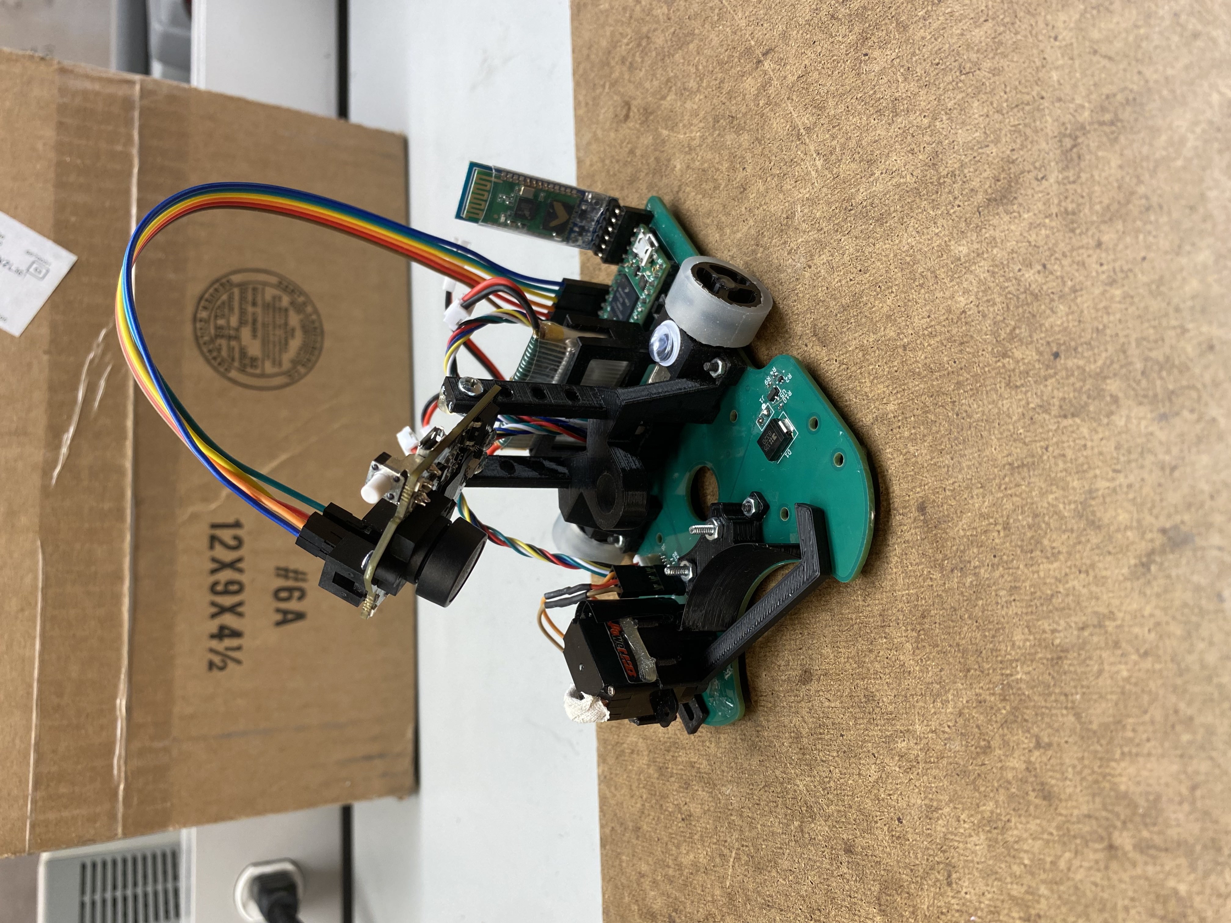
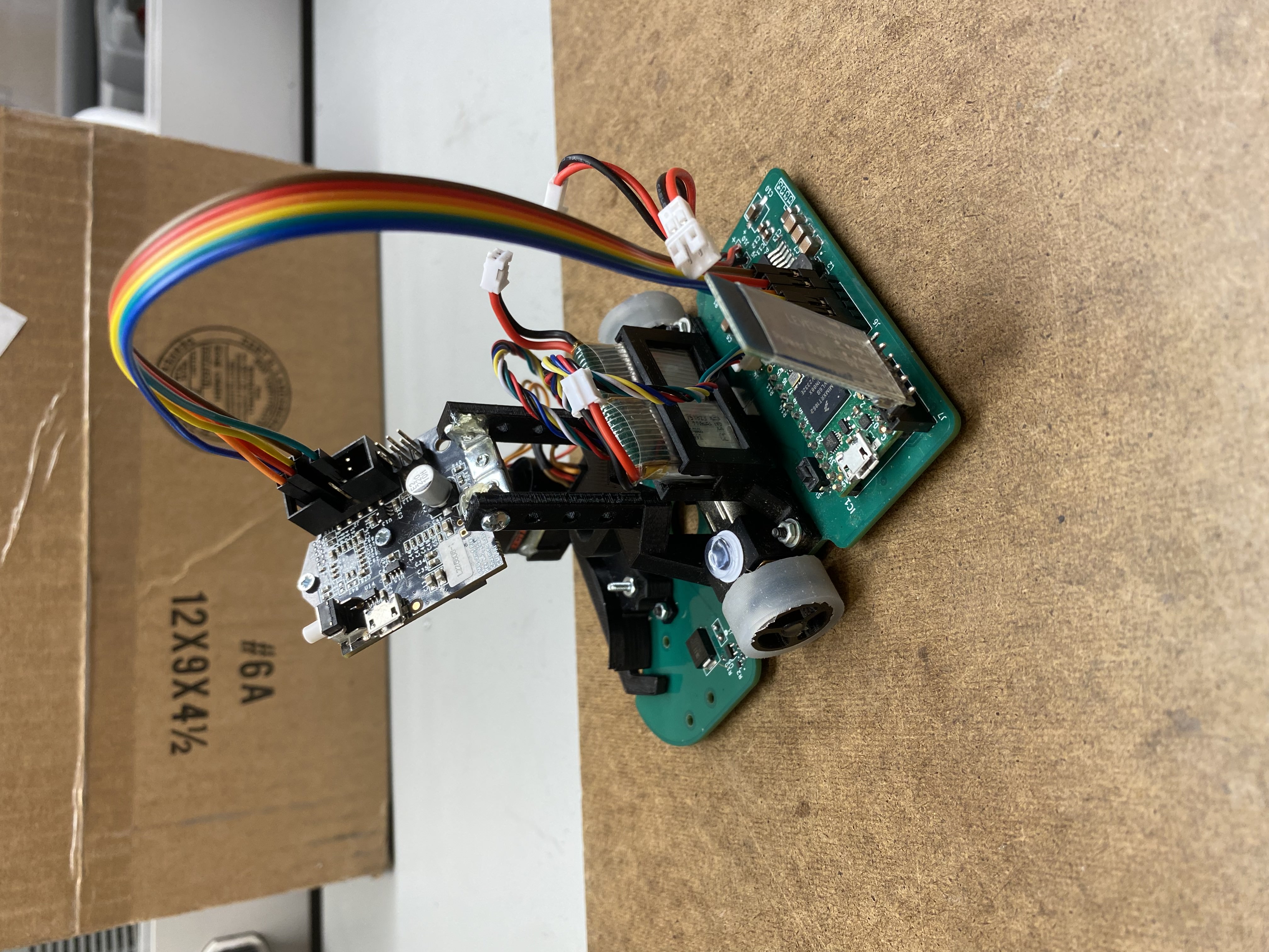
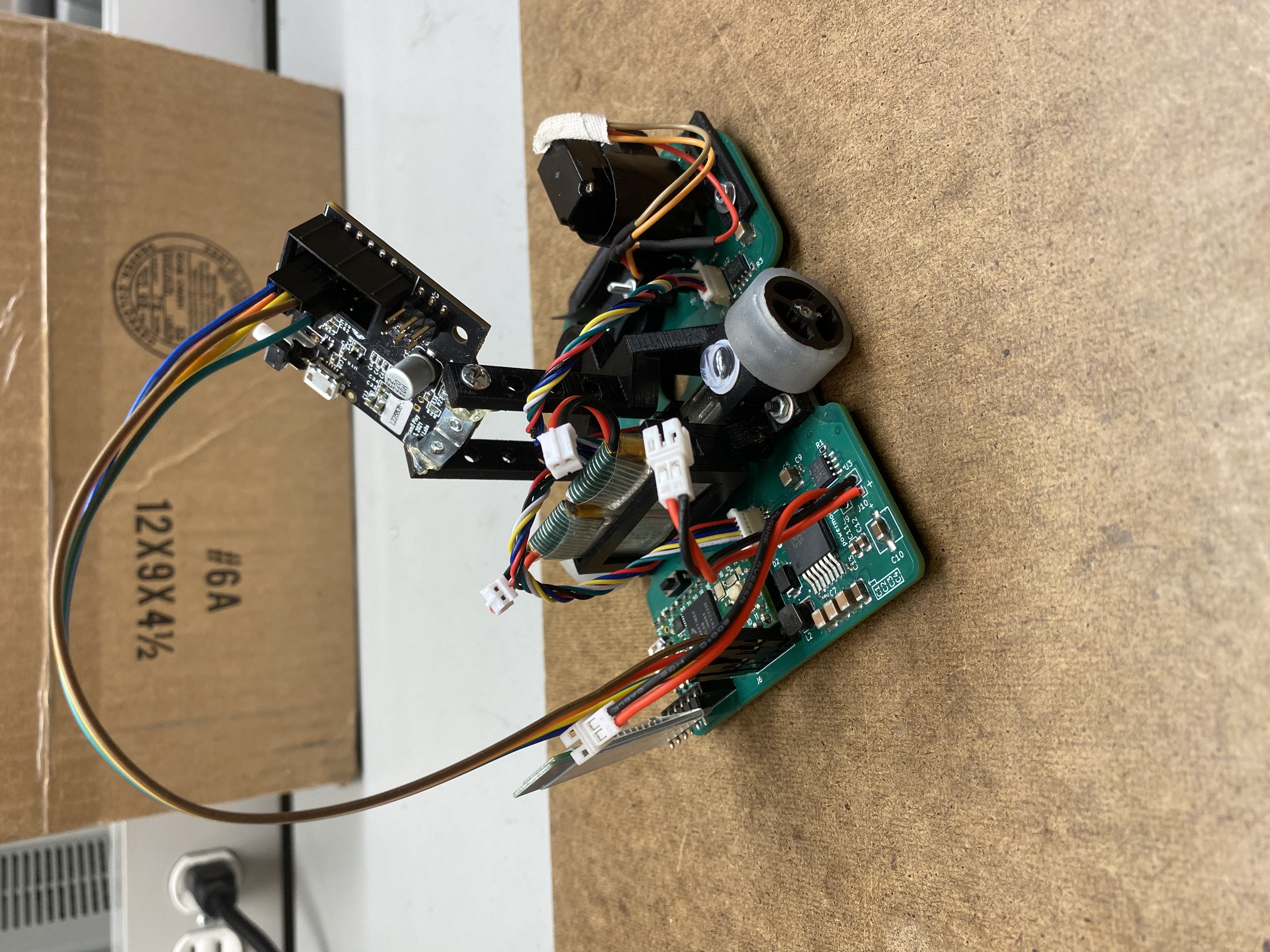
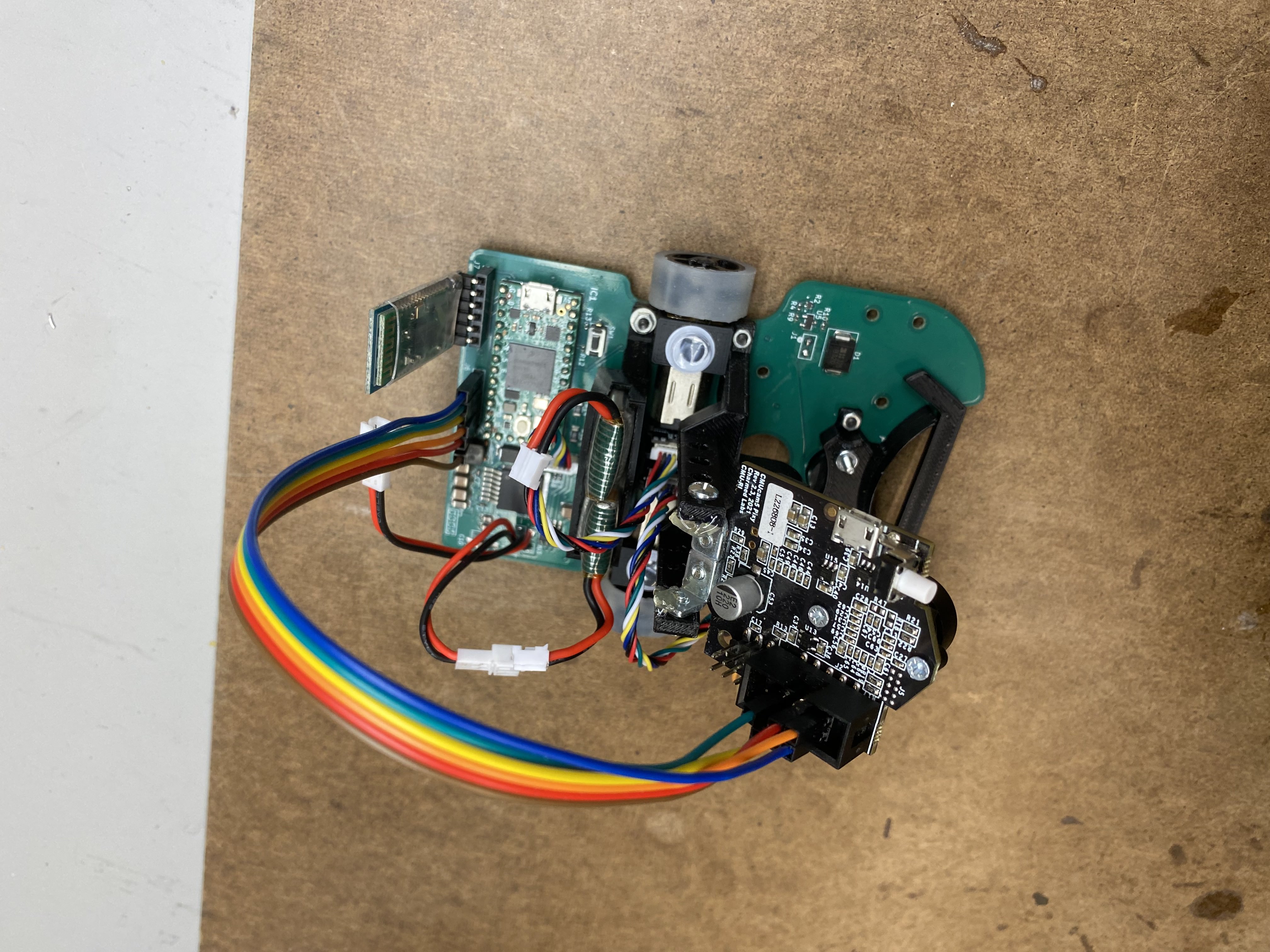
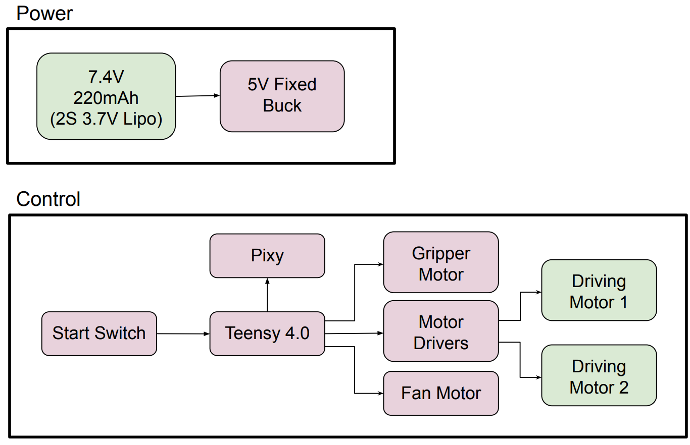
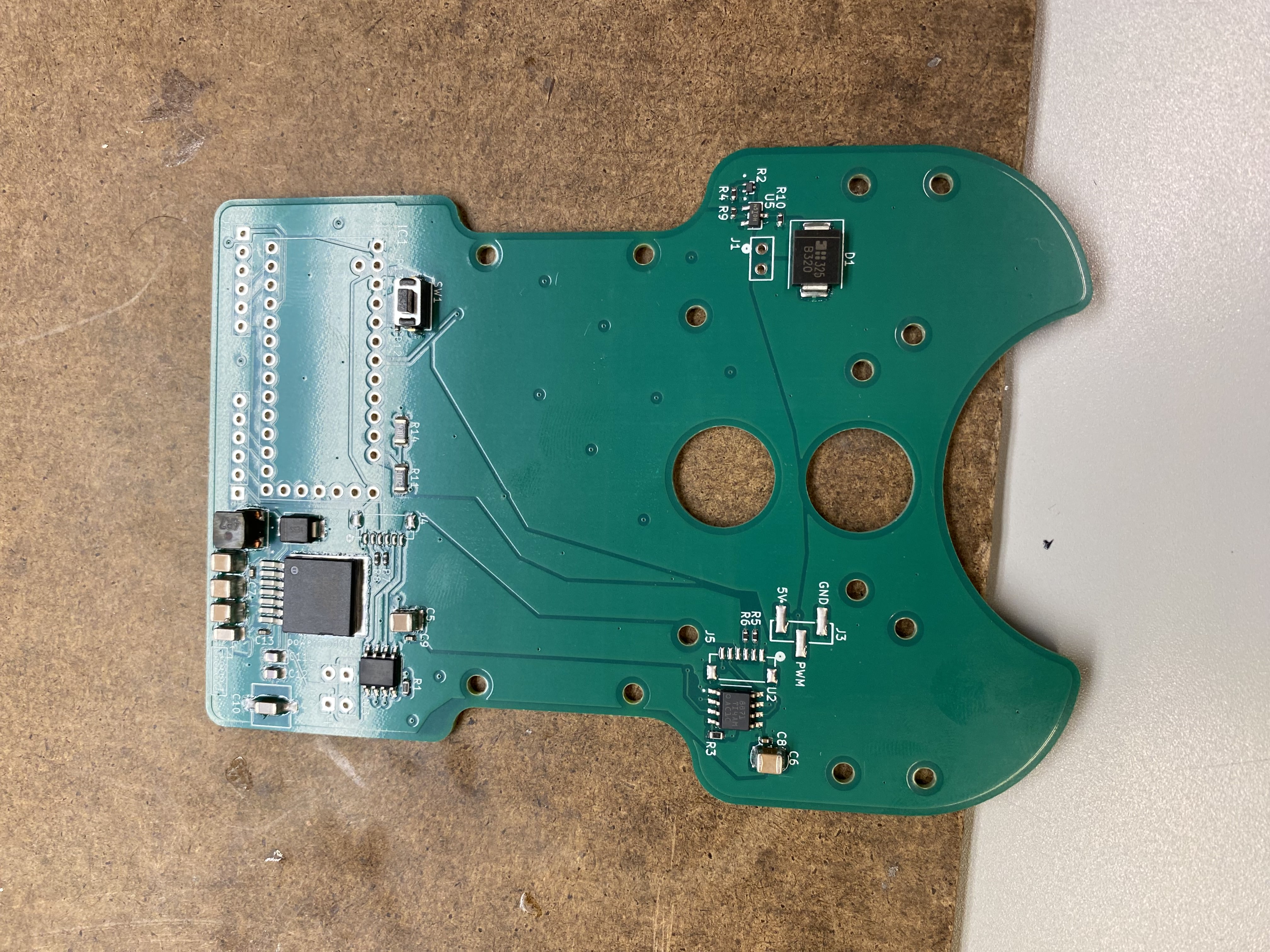
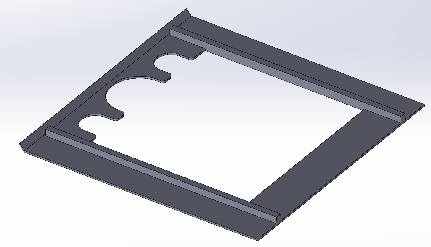
PCB as chassis. Instead of mounting electronics on a 3D-printed frame, the PCB is the frame. A 4-layer KiCAD board provides structure while integrating all electronics:
- Teensy 4.0 MCU (SPI to Pixy 2.1)
- 2× DRV8871 motor drivers
- LM22670 5V/5A buck converter
- FET drivers for fan motor and gripper servo
- Encoder signal traces routed on isolated layers to reduce noise
- PCB cutouts for LEGO gripper mechanism and suction impeller clearance
Why the Teensy 4.0. Its 600 MHz Cortex-M7 left ample headroom to run the PD control loop while streaming Pixy 2.1 vision data over SPI without dropping cycles — an Arduino-class ATmega would have bottlenecked the loop. It also exposed the hardware SPI, PWM, and encoder-capable pins needed for the motor drivers, servo, and fan FETs, all in a footprint light enough to matter under a mass-squared performance index. We didn't need onboard wireless (the main draw of an ESP32), so Bluetooth was added as a separate module only on V2, where live debug was worth the weight.
Power: 2× 3.7V LiPo in series (7.4V nominal, 6g each). Battery sizing from component power budgets:
Ibat = Ptotal / Vbat = 36.197 / 7.4 = 4.89 A
Capacity = Ibat × trun = 4.89 × (360 / 3600) = 489 mAh
C-rating selection for 4.3A peak draw across candidate cell sizes:
| Cell capacity | Min C-rating required |
|---|---|
| 500 mAh | 9C |
| 1000 mAh | 5C |
| 2000 mAh | 2C |
| 3000 mAh | 1.5C |
Tradeoff: lower capacity + higher C-rating handles peak current bursts but limits runtime; higher capacity + lower C-rating lasts longer but sags under peak loads. Used leaded solder on the final board for fatigue resistance against vibration.
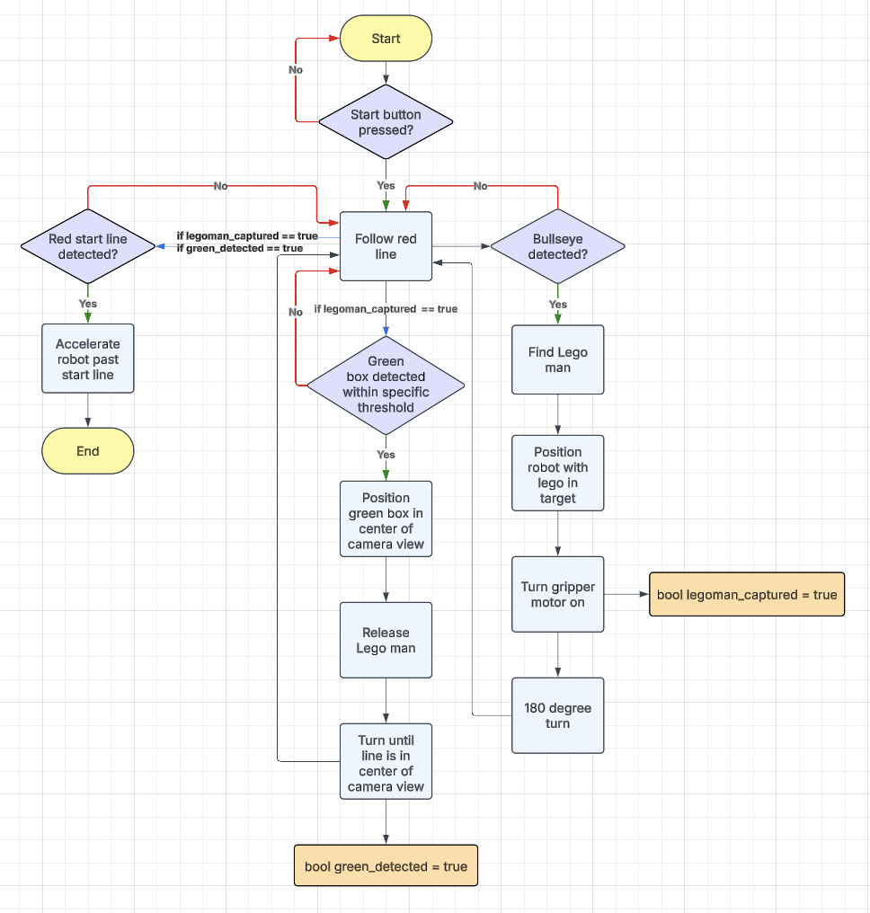
Control architecture. Deterministic state machine: line-follow → figure-detect → pickup → deliver → stop. PD controller uses the Pixy 2.1 vector offset from frame center as the error signal. Chose PD over PID; steady-state error was negligible and I-term integration would add lag at speed. Built separate Pixy signature configs for indoor vs. outdoor ambient lighting variations.
Wheels. Custom silicone (A20 durometer) cast in 3D-printed molds. Early ribbed-rim versions introduced lateral tracking instability that made PD tuning inconsistent. Switched to smooth rims. Tracking improved significantly. μ ≈ 1.2 measured via ramp-slip test (tan θ at slip onset).
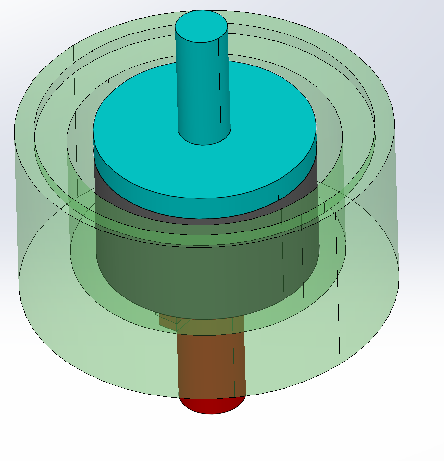
Suction downforce. Cornering speed without artificial downforce is bounded by
v_max = √(μrg). Adding suction increases normal force without adding
driven mass, improving the speed term in the PI formula without the mass penalty.
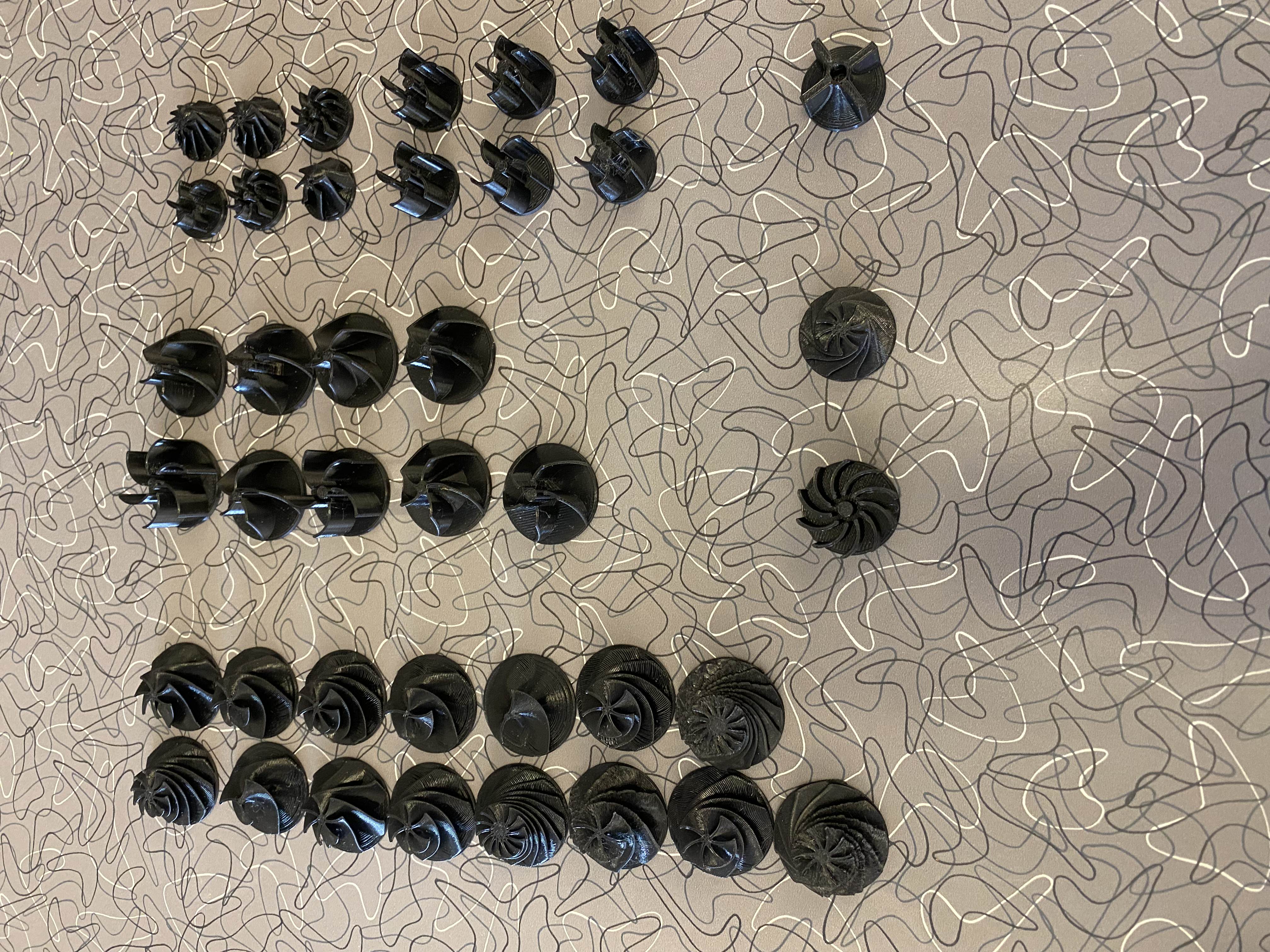
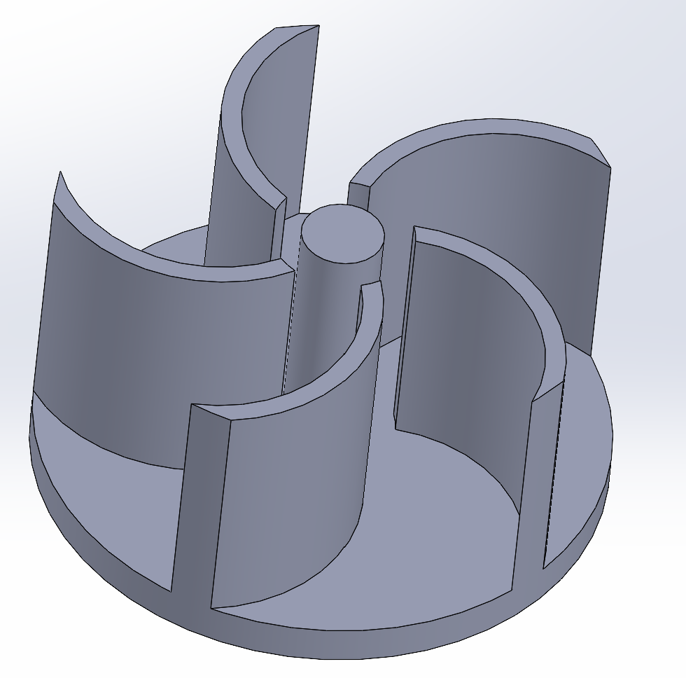
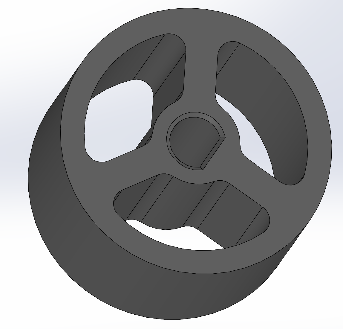
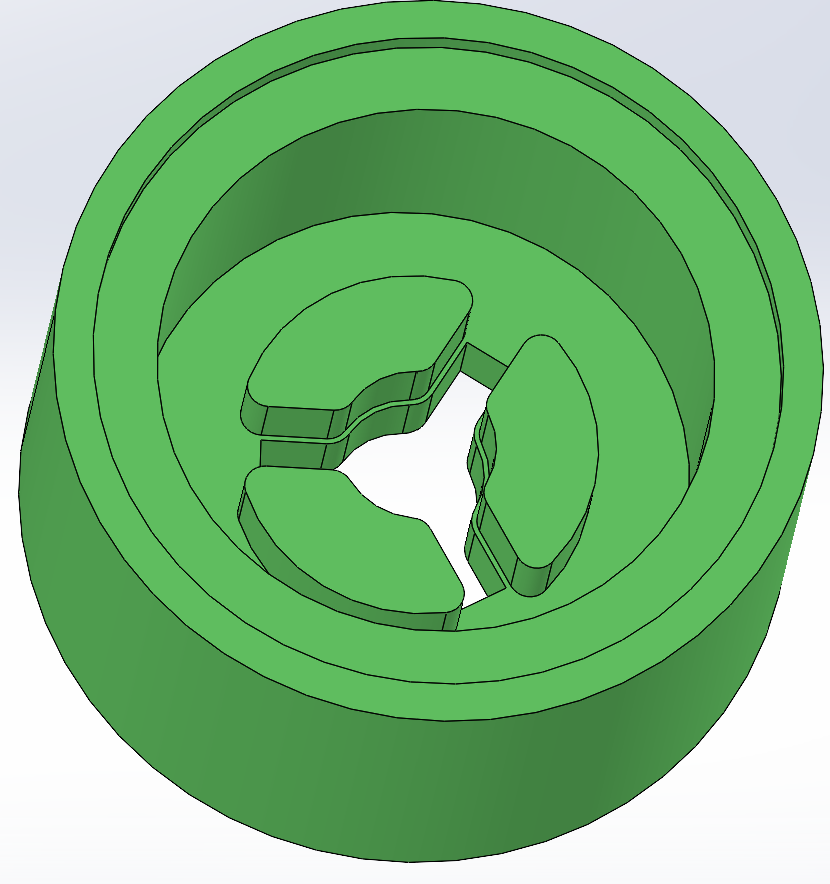
Parameterized impeller design across 8 variables: blade count (2–14), blade pitch (15–35mm), curvature (45–60°), diameter (12–30mm), height (10–15mm), cut shape, impeller style, and skirt geometry. 3D-printed 70 variants; each tested on a ramp fixture at fixed 5V/0.5A, 5 timed runs per variant.
| Configuration | Avg ramp time | Relative traction |
|---|---|---|
| No fan (baseline) | 0.84s | 1× |
| Compression, 5-blade | 21.1s | 25× |
| Radial, 5-blade (final) | 55.1s | 65× |
Theoretical cornering speed improvement: 1.33 → 1.40 m/s (+5%). Cut 3 days before competition. Last-minute motor vendor substitution disrupted the power budget and caused intermittent failures in the Pixy and gripper systems. Right call: the last 72 hours needed all five team members focused on full-course reliability.
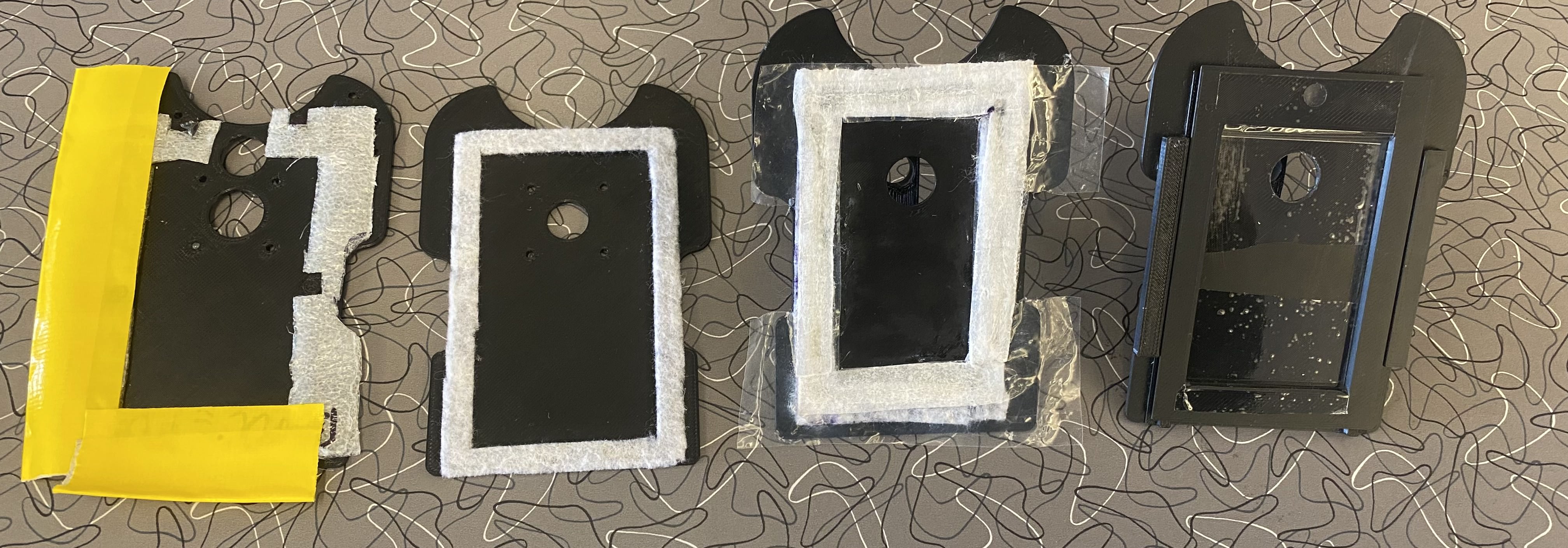
Gripper. Servo-actuated arm, 15 design iterations. Final version: foam dampening to absorb vibration noise, sloped LEGO backboard to prevent figure snagging during high-speed approach. A "jitter" pulse (high PWM for 20ms) allowed precision movement in the sub-60/255 PWM range where the motors stall under load.
PCB debug. V1 board had a floating servo ground pin causing unpredictable behavior. Systematically traced from known-good pins outward until the fault was isolated. V2 board added a Bluetooth module for live serial debug without the data-logging overhead that was starving the control loop on V1.
Rules insight. Only team to stop at the nearest green drop-off zone rather than returning to origin; the rules allowed it. Saved meaningful time in every run.
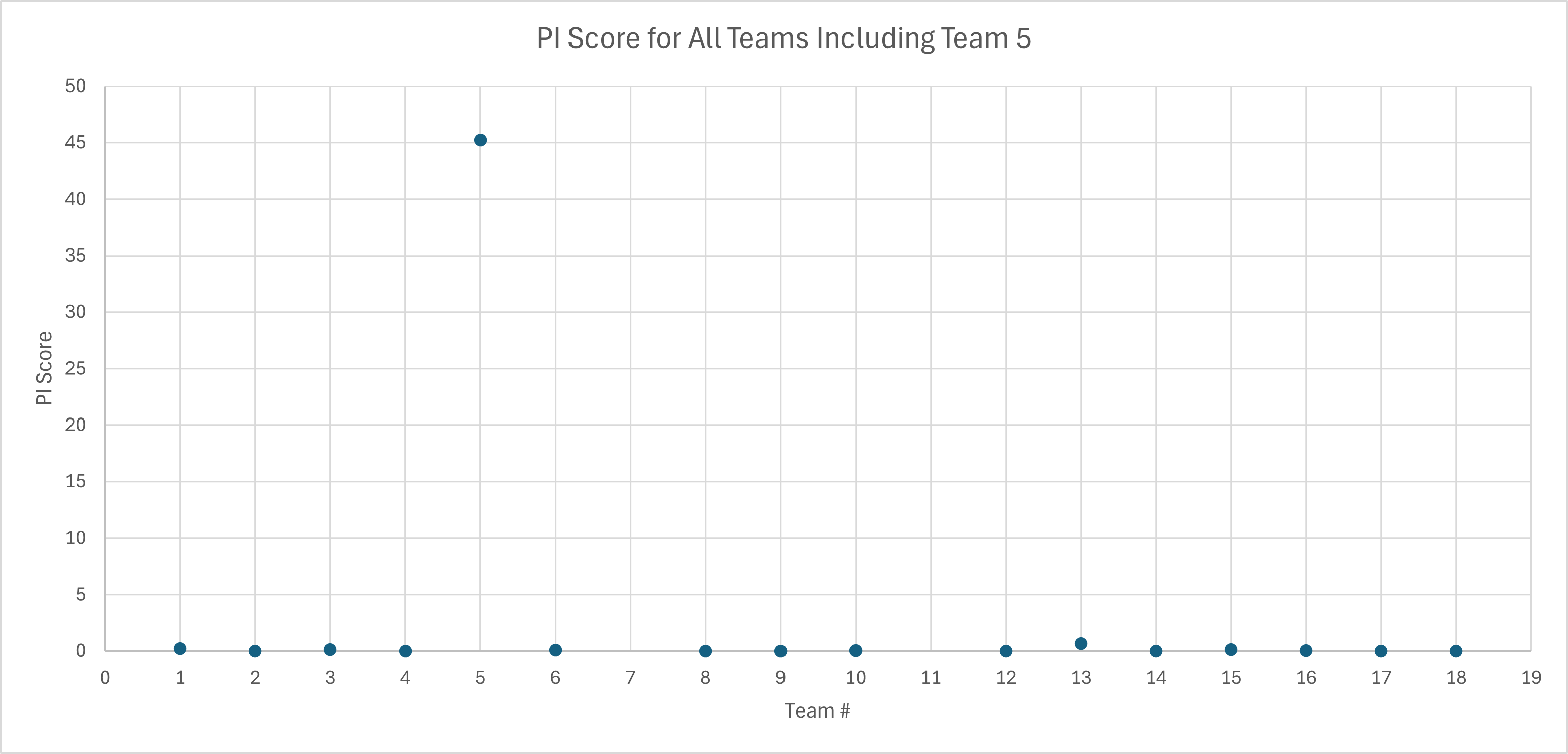
First place in MTE 380 with a performance index 68× higher than the second-place team.
| Metric | Value |
|---|---|
| Weight | 131g |
| Mission time | 13.0 s |
| Size | 114 × 86 mm |
| Reliability | 3/3 successful runs |
| PI vs. 2nd place | 68× |
Best run (13s) and the 360° robot walkthrough.
Technical report includes detailed design analysis, full impeller test data, PCB schematics, and state machine documentation.