Two parallel problems: business-critical CAN PCBs needed reliable, repeatable testing at production scale with a full data record per unit. Separately, drivers repeatedly forgot to raise the boom before connecting trailers, a recurring ~$200k damage event with no automated safeguard.
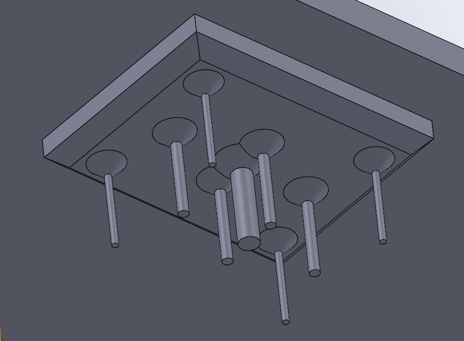
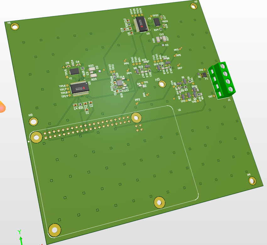
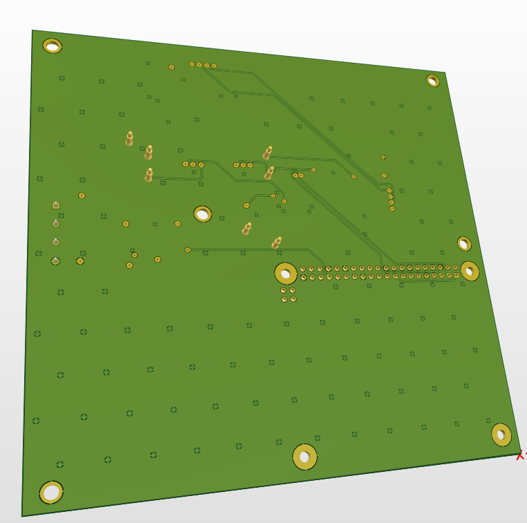
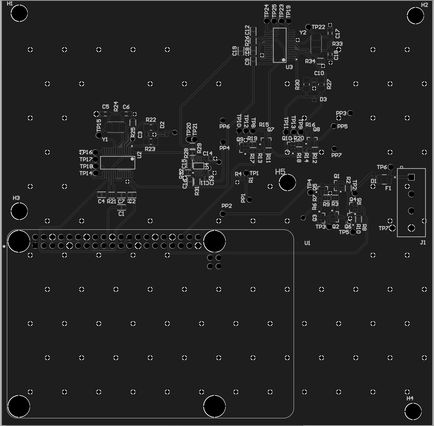
Designed a pogo-pin control PCB in Altium that interfaces as a hat on a Raspberry Pi 4. The board supports three test categories per unit:
- ±12V power rails: pass/fail continuity and voltage level
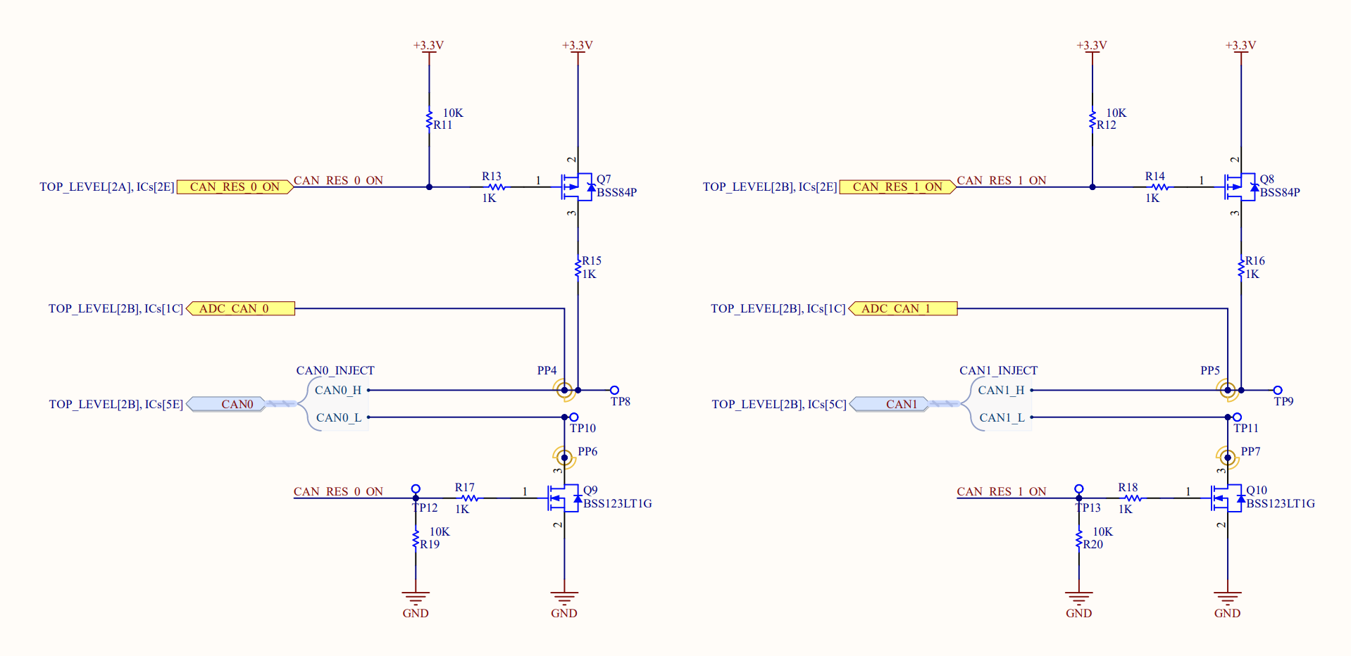
- CAN bus termination resistance: measured value within tolerance window
- CAN communication: live message exchange confirming bus integrity
PyTest sequences each check, logs results with timestamp and unit ID to Google Sheets for full traceability per PCBA at production scale. Chose PyTest for its error reporting granularity and the ability to re-run individual failed cases without re-running the full suite.
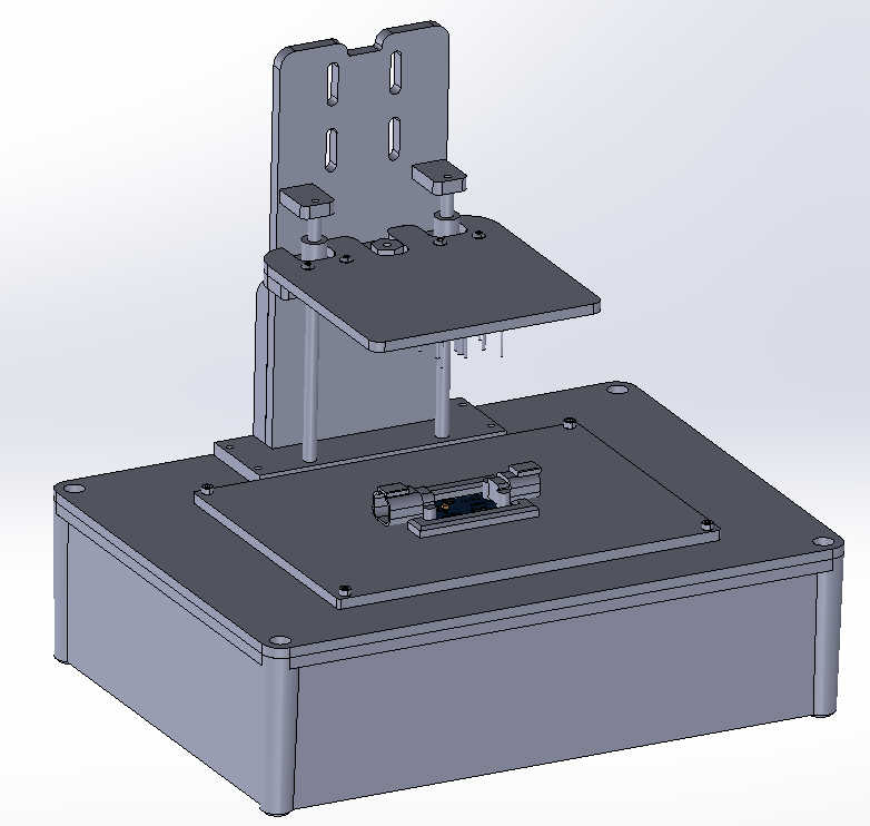
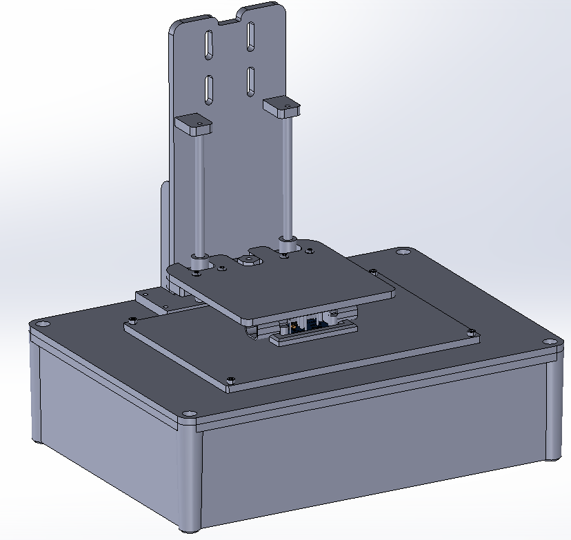
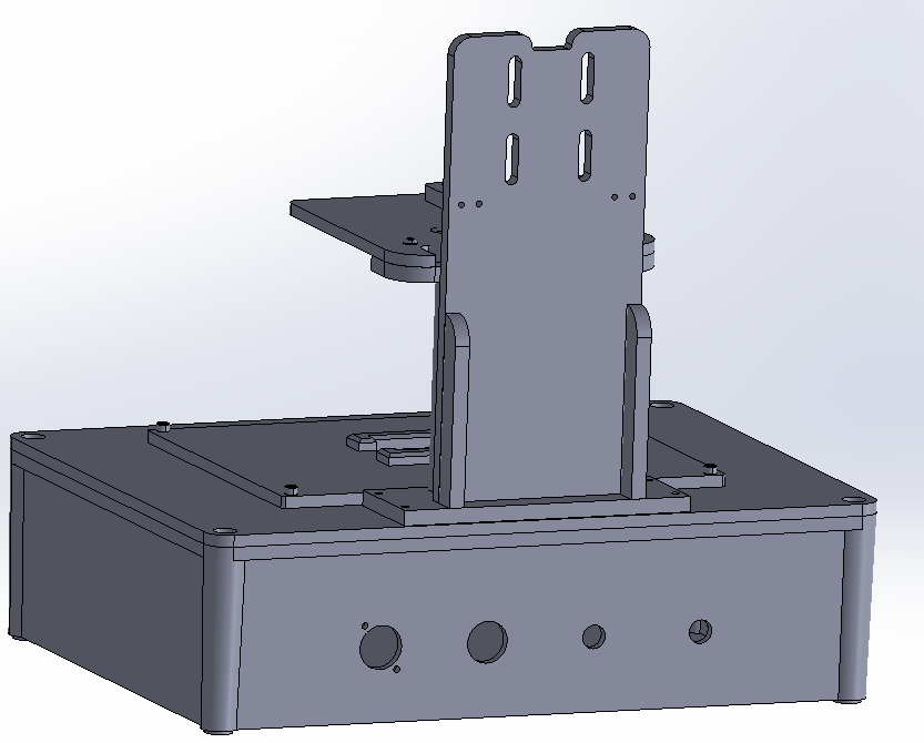
Enclosure: off-the-shelf McMaster-Carr box (oversized by design to future-proof for additional test points). 3D-printed swappable center plate per PCB variant, 3D-printed pressing plate to protect DUT components. Modular by design, swapping boards under a minute.
Requirement: detect when the trailer angle exceeds 5° (2° threshold + safety margin) and automatically raise the boom. The spec started at ±0.5° and migrated to ±0.1° mid-project, a requirement I ultimately pushed back on.
Iterated through three approaches as the accuracy spec kept shifting:
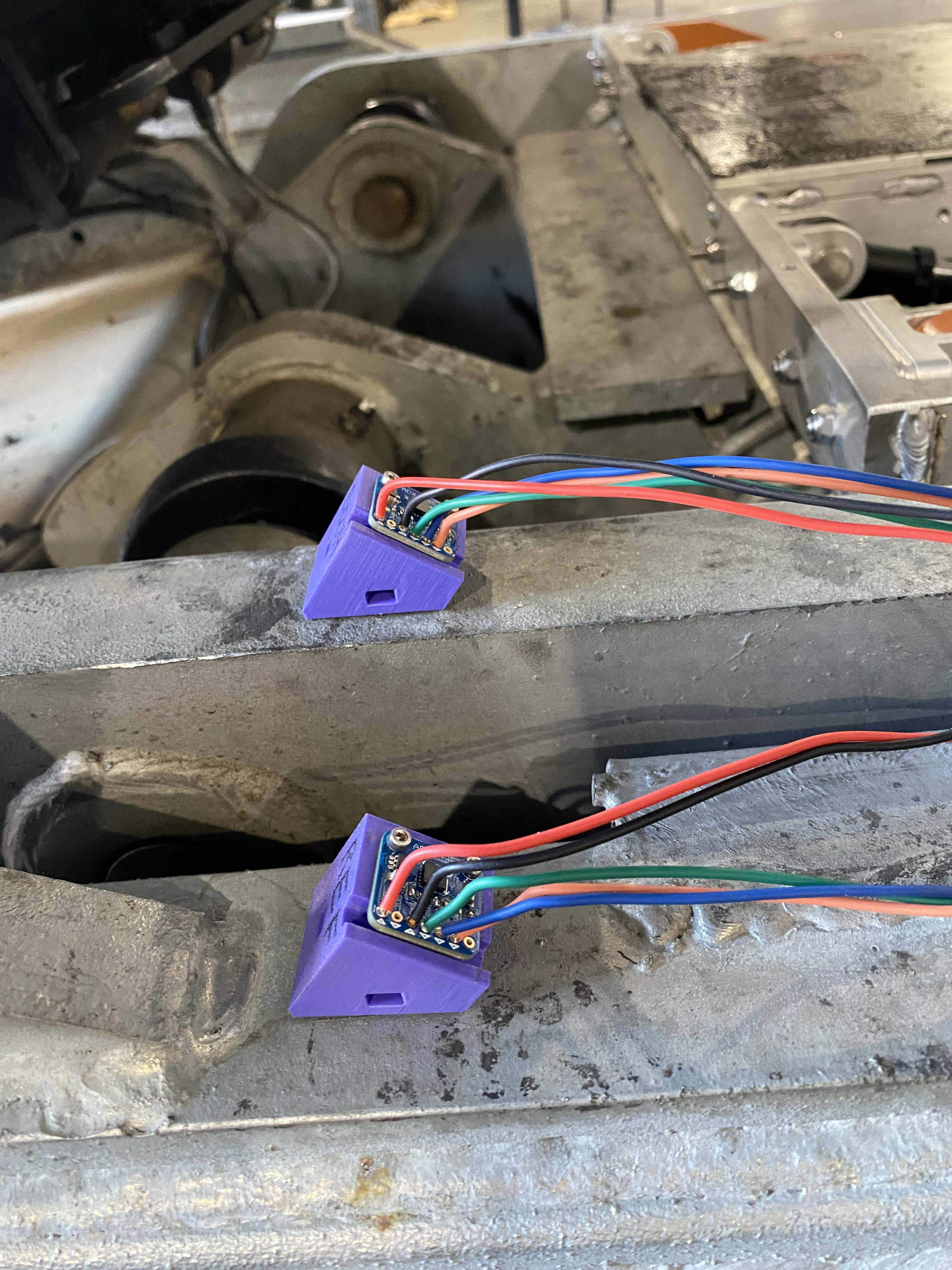
- ADXL335 (3-axis analog). Smoothing algorithm over 20 samples, mounted at 45° to maximize accuracy in the 35–55° range. Met original ±0.5° spec in 9 static + dynamic test cases across two days. Team then moved the goalposts to ±0.1°.
- Murata SCA830-D07 (single-axis SPI, automotive grade). No breakout board existed, so I designed a custom PCB. During schematic review, another hardware failure occurred on the truck.
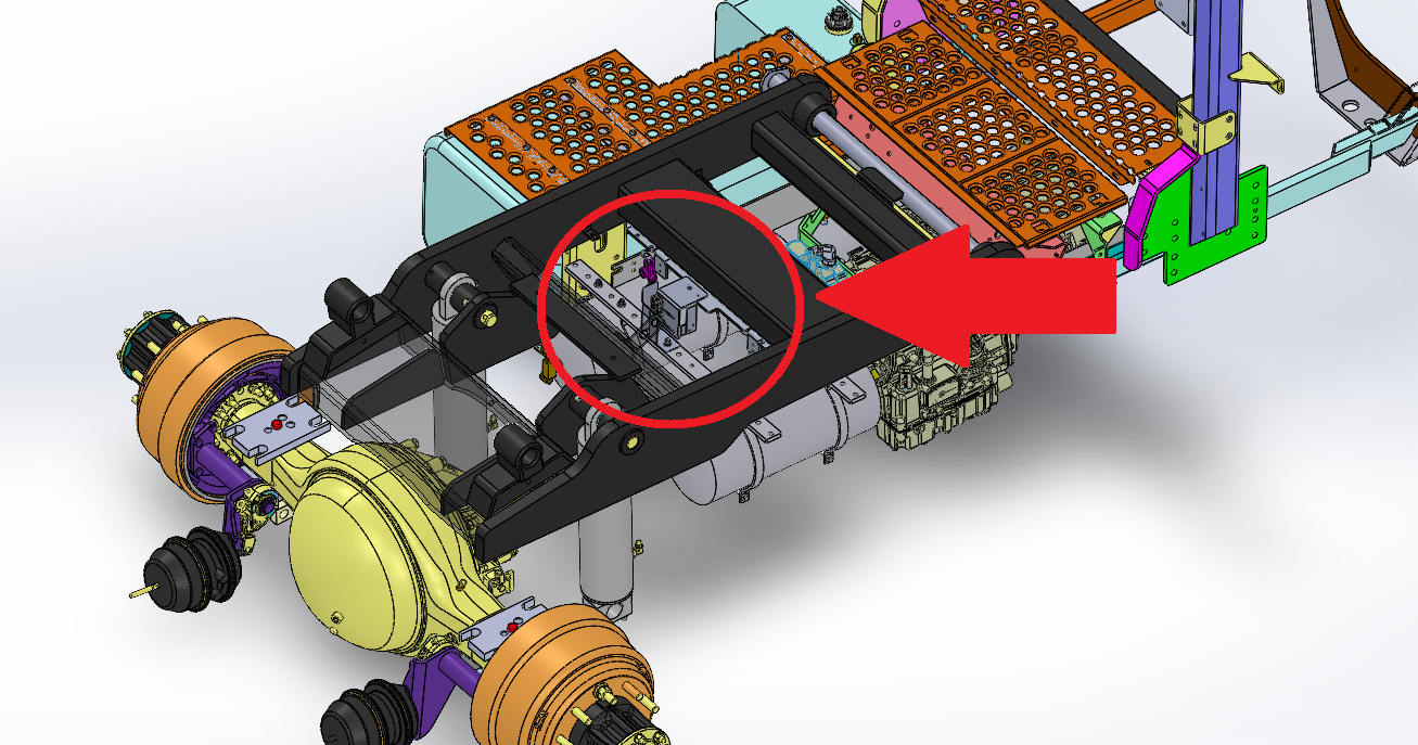
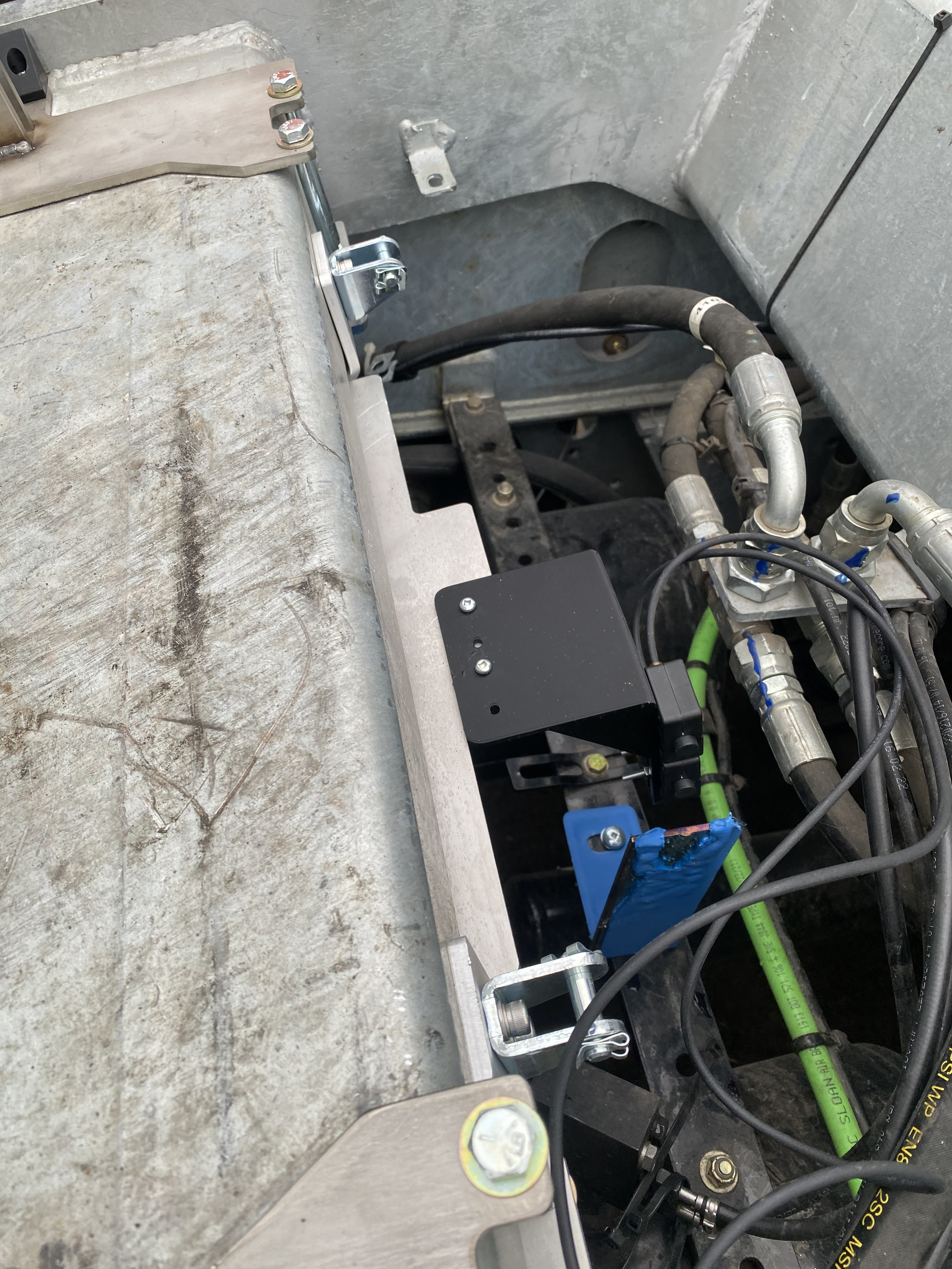
- Binary proximity detection. Pushed back on the ±0.1° requirement as unjustifiable for a binary safeguard. Designed two sheet metal brackets: sensor mount and target flag. When the boom raises past threshold, sensor goes low. Simple, cheap, fast to deploy.
Final solution communicates via CAN to the boom pump ECU, uses existing truck mounting holes, and requires no additional enclosure. Prototype accuracy: ±0.5° static. A better answer to a simpler requirement.
Bed-of-nails fixture in production use. Boom control deployed on trucks. Connector cost reduced 80% via PCBA layout and overmold optimization, a separate scope item from the two main projects.